Index
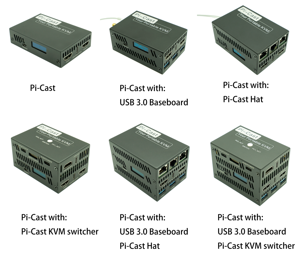
Pi-Cast is a portable Raspberry Pi based KVM over IP device that allows you to managing servers or workstations remotely, whatever the state of the operating system or whether the operate system is installed.
Pi-Cast allows you to turn on/off or restart your computer, configure
the UEFI/BIOS, and even reinstall the OS using the Virtual CD-ROM or Flash Drive.
Pi-Cast can simulate a keyboard, mouse, and a monitor,
which are then presented in a web browser as if you were working on a remote system directly.
Pi-Cast also provides the ability to cast any HDMI source to your iPad, iPhone, Mac, Android device, or any other platform with support for USB Ethernet. It does so at full bandwidth, using a single USB Type-C cable, and without the need for networking equipment of any kind. And it's tiny. Thanks to its Raspberry Pi 4B form factor, it measures just 85 x 56 x 15 mm. That gives it a footprint smaller than that of a credit card and makes it the most compact PiKVM device on the market.
Features
- Support for 1920x1080 resolution at 60Hz for improved UEFI and BIOS compatibility
- Support for USB device simulation, including emulated keyboard, mouses, mass-storage devices, etc.
- Support for simulating USB insertion and removal events
- Pi-Cast HAT
- An RJ45 ethernet port with PoE support
- A real-time clock (RTC) with a battery holder
- ATX control through RJ45 (compatible with the official PiKVM HAT)
- A USB serial port to access PiKVM
- A Cisco-style console port (to access PiKVM or servers)
- A fan with speed control
- A PoE module
- An OLED screen
- A 40-pin Raspberry Pi header
- Pi-Cast KVM Switch
- Multiport switching with ATX support
- USB HUB
- Manual switching button
- LEDs for indicating active connecting computer
- A fan with speed control
- A PoE module
- USB Type-C power port
- USB-Serial control port
- GPIO control header
- PCIe-to-USB-3.0 Baseboard
- Three USB 3.0 Type-A ports
- M.2 B Key interface for an LTE/5G roaming card
Technical Specifications
- HDMI input (implemented by TC358743XBG)
- HDMI output
- Onboard, USB-3.0 Gigabit Ethernet
- USB 2.0 Type-C(client & host)
- SD card slot (for CM4 versions without eMMC support)
- 40-pin Raspberry-Pi-compatible pin header
- Size: 86 x 56 x 15 mm
IO Diagram
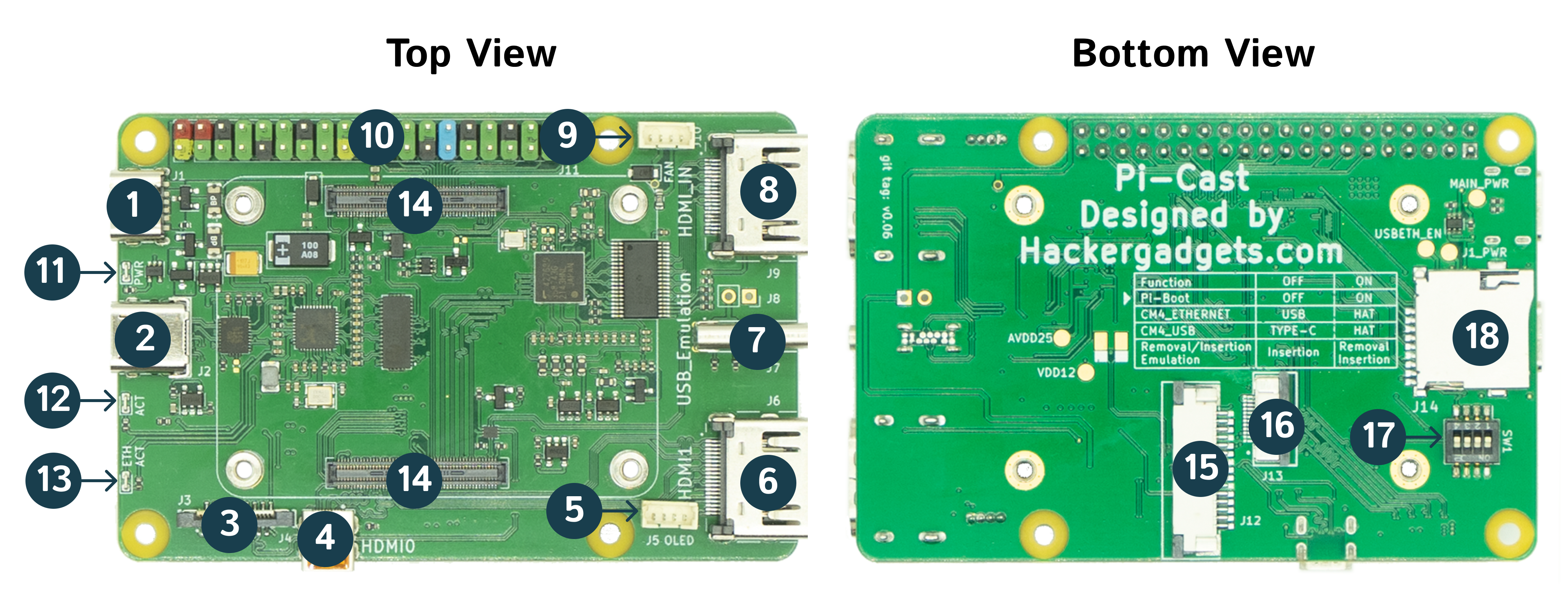
- Main power input
- USB 3.0 Ethernet(Can be used as power input)
- FPC connector for hat board(ethernet signal, CM4 USB, Run Flag and global enable)
- HDMI0 output
- OLED connector
- HDMI1 output
- Type-C USB simulation port
- HDMI input
- 5V PWM Fan connector
- 40 Pins GPIO Header(compatible with Raspberry Pi 4B)
- CM4 power Led
- CM4 activity Led
-
USB 3.0 Ethernet activity Led
Led status Meaning solid ethernet connected blinking network activity -
CM4 Module Connector
- 2-lanes CSI-2 15 pins FPC connector
- PCIe fpc connector
-
Position Function OFF ON 1 Pi-Boot OFF
(booting from eMMC or TF card)ON
(booting from eMMC is disabled and the bootrom will wait for code over USB instead)2 CM4 ethernet routing Route to J2(USB 3.0 ethernet) Route to J3 (Hat board FPC connector) 3 CM4 USB routing Route to J7(Type-C USB simulation port) Route to J3 (Hat board FPC connector) 4 USB Removal/Insertion Emulation Always Insertion Removal/Insertion(controlled by GPIO5, 0:Removal 1:Insertion) -
TF Card Slot for CM4 Lite
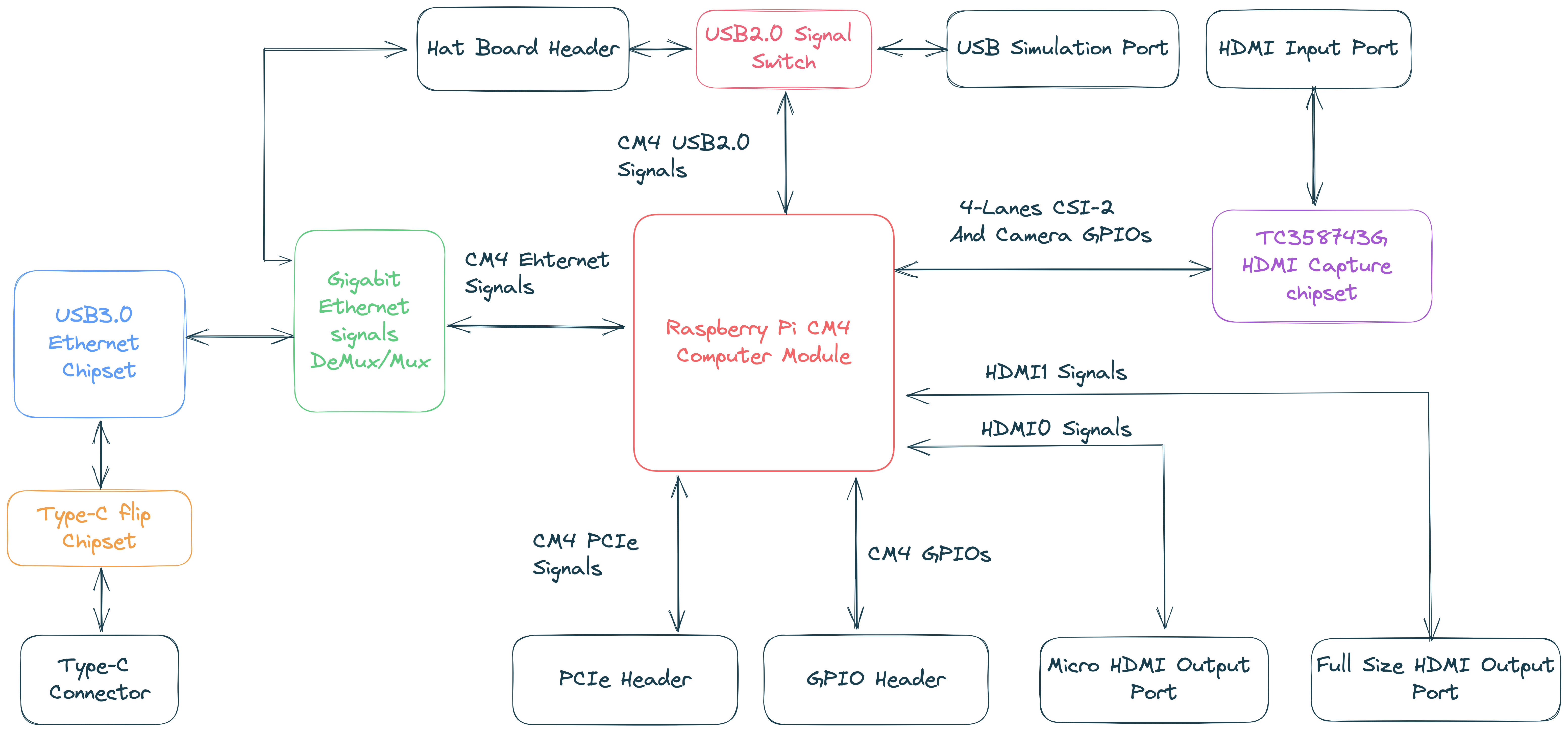
System Block Diagram
GPIO Pinout
Before using GPIO pins to control a relay, KVM switch, or anything else, be sure to check the below table. Many ports are busy with internal functions. Before using them for your own use, you must disable them, otherwise you may damage the device.
| Pi-Cast | PiKVM V3 Hat | PiKVM V4 Plus&Mini | |
|---|---|---|---|
| I2C bus | GPIO 2,3 |
GPIO 2,3 |
GPIO 2,3 |
| UART | GPIO 14, 15 |
GPIO 14, 15 |
GPIO 14, 15 |
| Fan PWM pin | GPIO 12 |
GPIO 12 |
GPIO 13 |
| Fan hall pin | GPIO 6 |
- | GPIO 16 |
| USB breaker | GPIO 5 |
GPIO 5 |
GPIO 22 |
| I2S audio | GPIO 18, 19, 20, 21 |
GPIO 18, 19, 20, 21 |
GPIO 18, 19, 20, 21 |
| ATX Power led | GPIO 24 |
GPIO 24 |
GPIO 4 |
| ATX HDD led | GPIO 22 |
GPIO 22 |
GPIO 5 |
| ATX power switch | GPIO 23 |
GPIO 23 |
GPIO 23 |
| ATX reset switch | GPIO 27 |
GPIO 27 |
GPIO 27 |
| Locator | - | - | GPIO 12 |